|
|
The Restoration of the PDP-8/I Minicomputer (PAGE 3)
Given that the basic unregulated voltages were within spec, my buddy and I took a high wattage (25 W)
low resistance (4 ohms) resistor and placed that across the 5 VDC regulator outputs to give it a useful
load.
We turned on the power supply, and cranked the variac from 5 VAC to 120 VAC in the span of about a minute
to observe the power curve.
It was sweet -- the voltage on the output of the regulator gradually increased with the input voltage and
then simply stopped dead at 5 VDC.
|
During the time that the variac ramp-up was occurring, I did two types of visual inspection:
- Card position
- Backplane
 S
M
L
XL
These are the cards in the PDP-8/I.
Click here for an annotated picture.
S
M
L
XL
These are the cards in the PDP-8/I.
Click here for an annotated picture.
|
The card position inspection simply involves comparing the 8/I module utilization chart with the actual
modules installed.
I found that I was missing an M651 card -- luckily I had one in spares.
Two of the M113 cards were slightly damaged (handles broken) so I replaced those as well.
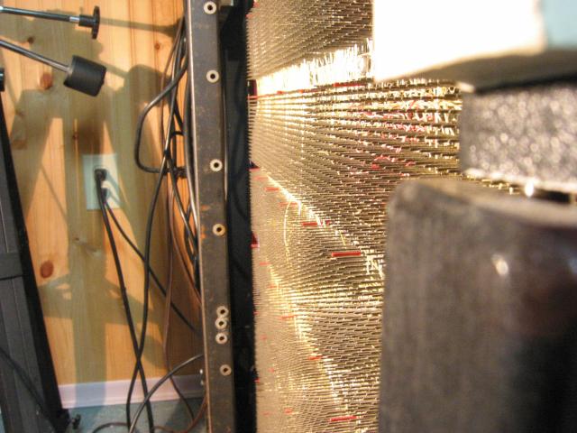
Two different angle views of the PDP-8/I backplane (shot from the front in the first, and the front is on the right hand side in the second);
note in the first picture that even though I straightened out all the pins
I found that were bent, there are still bent pins.
The second picture is a face view of the backplane.
|
The backplane inspection involves sighting down the backplane at +45, 0, and -45 degree angles.
At these angles, the pins line up nicely, and you can tell if there are any bent pins.
You need to do it in all three directions (hence the "+" and "-") to get the majority of them.
Of course I had some bent pins so I straightened those with my finger.
|
|
|